

Daimler Daimler 22 1902- 1903
| Daimler 22 hp | |
|---|---|

4½-litre 4-cylinder 1903
nascent flutes on the radiator's side tanks |
|
| Overview | |
| Type | car (also available as a chassis only) |
| Manufacturer | Daimler Motor Company |
| Production | July 1902 to December 1903 |
| Designer |
|
| Body and chassis | |
| Class | Full-size luxury car (F) |
| Layout | front engine, rear-wheel-drive |
| Related |
|
| Powertrain | |
| Engine |
|
| Transmission | leather-lined clutch, flexible jointed splined propellor shaft to 4-speed and reverse gearbox enclosed as a unit with differential and countershaft in an aluminium casting. final drive by sprockets and side chains. |
| Dimensions | |
| Wheelbase |
|
| Kerb weight | 2,500 lb (1,134 kg) bare chassis |
| Chronology | |
| Predecessor | 16/18 |
| Successor | 18/22 |


| Daimler 22 horsepower |
|
|---|---|
design for 4½ and 3.4-litre engines
|
|
| Overview | |
| Manufacturer | Daimler Motor Company |
| Combustion chamber | |
| Configuration | vertical inline 4-cylinder |
| Displacement | 4,503 cc (274.8 cu in) |
| Cylinder bore | 105 mm (4.1 in) |
| Piston stroke | 130 mm (5.1 in) |
| Cylinder block alloy | cast iron. twin-cylinder blocks installed in pairs |
| Cylinder head alloy | cast with cylinder block |
| Valvetrain |
|
| Combustion | |
| Fuel system |
|
| Fuel type | petrol |
| Oil system | piped pressurised by exhaust system |
| Cooling system | water, centrifugal pump, fan, radiator |
| Output | |
| Power output |
|
| Chronology | |
| Predecessor | 16/18 |
| Successor | 18/22 |
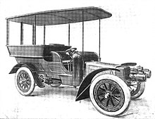
Their new Daimler 22 horsepower full-size luxury car was first displayed by Daimler in April 1902 at The Automobile Club’s Exhibition in London's Agricultural Hall.
Daimler had elected to drop their multiple old low powered designs and restrict themselves to this 22 horsepower and a pair of 9 or 12 horsepower cars to the same design as the 22 but more lightly constructed. The King’s not quite finished new Daimler 22 was reported to be the chief attraction of the show.
The 22 horsepower cars were geared to run at about 40 to 50 miles per hour when the engine was running at normal speed.
The following January 1903 Daimler, having earlier dropped the 9 hp, replaced their 12 with a 14-horsepower car making a range of just two vehicles.
In January 1904 Daimler introduced a wholly new range of four cars including a 3.8-litre 18/22.
New range
The 4½-litre 22, and its 3.4-litre stablemate the 12, were developed and their construction organised by Percy Martin then works manager. The twin-cylinder 9 hp car was soon dropped. Although they were first displayed in April deliveries did not begin until July and a steady production stream did not eventuate until November 1902. These new models were the product of the board's decision to end production of old type cars and restrict the range to two or three models with standardised interchangeable components. This new range was between 25 and 30 per cent lighter than their preceding equivalents and had much improved speed and hill-climbing power. All the wheels were now the same size. The redesigned steering helped to make them easier to drive. The lowered chassis frame increased the cars' stability and made entry easier. The more rigid chassis frame improved the alignment of the transmission system. Finally this new model cost 17 per cent less to manufacture than its predecessor.

standard body |

at Medlow Bath NSW Australia |
Bodies
Standard bodies were built in Daimler's own body department which would also provide bespoke bodies on different wheelbases to special order. Chassis were made available to customers' own coachbuilders. The same body was used on the 22 hp as on the 9 and 12 hp chassis.
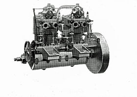
Engine
The 4-cylinder, 4½-litre side-valve engine is a pair of cast iron twin-cylinder blocks bolted to an aluminium crankcase cast in upper and lower halves.
It develops 22 hp at 720 rpm at which speed in top gear the car should be running at between 40 and 50 mph.
The engine's governor regulates by suspending the action of the exhaust valves consecutively. There are also throttle valves under the control of the driver.
The four forward speeds are selected by one lever, reverse by a small lever on the footboard.
| The engine uses splash lubrication. The crankcase walls are cast with oil-ways in which oil is caught and led to the main bearings then thrown by centrifugal force to the big end bearings of the connecting rods. A thin sheet of metal with a hole for the connecting rod closes the bottom of the cylinder so the piston is not flooded with oil.
The inlet valves and exhaust valves are arranged facing each other, the inlet valve above. The inlet valves are held in place by the induction pipe from the carburettor which encloses a throttle valve. Separate passages lead from the exhaust valves to the exhaust manifold. |

|
The crankshaft has three main bearings. Two double rings are fitted to the pistons. The skirt of each piston is reduced slightly in diameter to form an oil retaining space. The steel connecting rods are drop forgings. Gudgeon pin bearings are bushed with steel, the gun-metal big end bearings are lined with white metal as with all other bearings throughout the engine. The camshaft is driven from the crankshaft by spur wheel. The camshaft bearings are part of the crankcase covered by an upper half that is a separate casting and provides a guide for the pushrods. The camshaft’s forward end carries the centrifugal governor. A half-inch pitch roller chain links the drive to the commutator mounted on the car’s dashboard. The camshaft is lubricated by splash from the crankshaft. Throttle valves are worked by the driver.
- Dashboard
| The dash, fitted with cupboards for electrical equipment and tools, carried the engine-driven commutator, the engine's lubricators and a three-way tap. If the gauge glasses showed the lubricators were running low on oil they were refilled when the driver required using a pipe from the pressurised supply tank on the right side of the engine. The three-way tap allowed the driver to let water into the transmission brake's drum and it could also be used to bleed excess pressure in the oil or fuel systems. |

|
Electric ignition is fitted together with a supplementary Tube system. A combined igniter, a single plug, is screwed into each cylinder's valve chamber. At the opposite end from the valve chamber the tubes project into an enclosed metal casing where they are heated by lamp burners. They are so organised that if a lamp is blown out it will relight itself. But this hot tube ignition is just provided in case the electric ignition fails. Electric ignition is better because the timing of the ignition can be varied. |

|

- Fuel
Petrol is supplied by gravity from the tank at the rear of the car but once the car is under way exhaust gases maintain a pressure within this tank. A lubricating oil tank is pressurised the same way. The petrol tank is in two compartments separated by a partial partition. Both sections are filled when the tank is filled above that partition but when the larger tank is empty the second tank provides a fresh supply and a timely warning to the driver.
An exhaust box is mounted on the near (left) side between the countershaft and the back axle. After passing through this box the gases are led across the back of the car in a pipe with a perforated underside to minimise the dust stirred up.
- Cooling
The starting handle passes through a water tank at the front of the car. The radiator is fixed immediately above this tank. Its sides are of ribbed aluminium castings connected by finned tubes run horizontally across the front of the car. The ribbed aluminium castings inspired Daimler's flutes. The water circulating centrifugal pump is driven by a friction wheel pressing against the flywheel. Two pressure lubricators feed the pump's bearings. The design ensures natural circulation would continue if the pump were out of order. There is a sheet metal casing beneath the engine as a dust-shield.
Chassis


designer and works manager
Cartoon image from The Automotor Journal December 30, 1911
All four wheels were 36 inches diameter artillery style with steel axle boxes and thickened spokes to carry the chain drive sprocket wheels. Suspension was by “grasshopper” (semi-elliptical) springs 36” behind and 31” in front. Chassis weight under 22 cwt. Wheelbase 7’ 6” and the track or “gauge” 4’ 7½” The wheelbase of the King’s car had been increased to 9’ 0”.
The wooden main frame is strengthened by tapering steel fishplates along the inner faces of the longitudinal members. One of the transverse-members supports the change speed lever. From these transverse members an underframe is suspended and it supports the engine at a level below the main frame.
The clutch and flywheel are mounted on the back of the engine block This part of the clutch is of aluminium and carries a friction surface of leather To make for a more gradual engagement a steel spring is set between the leather and the metal face. It is formed into a ring with projecting tongues which ac t as springs. The large spiral spring to hold the clutch in engagement is stationary. It acts on the fork imparting a sliding motion to the propellor shaft. A ball bearing takes the thrust between fork and the shaft. A long propellor shaft runs from the clutch to the gearbox's first motion shaft. This propellor shaft carries a flexible coupling and is splined to allow longitudinal movement together with the clutch. The gearbox is mounted between the back axle and the sprocket shaft for the chain drive.
When the handbrake is applied the (otherwise fixed) end of the spring is moved forward by a cam which releases the clutch and the car may stop without affecting the engine. Application of the footbrake has the same effect. This arrangement was deleted from the next model now the driver has control of the throttles and engine braking may be used to reduce the load on the brakes.
The transverse casing of the countershaft the differential and the gearbox is of aluminium alloy and it covers the entire transmission gear. The change-speed lever is mounted on this casing. The transmission has eight ring-lubricator type bearings fed by pipes from feeders with gauge glasses visible from beneath the car. Power is transmitted from the transverse countershaft to each rear wheel by 1½ inch pitch roller chains. When necessary the complete gearbox may be removed downwards.
- Gearbox
Four forward speeds separate lever for reverse
- Brakes
The foot pedal operates by rod a transmission brake mounted on the rear end of the gearbox's second motion shaft. It is described as a powerful double-acting band brake. The brake's drum is surrounded by a water jacket. The hand lever operated side brakes (on the rear wheels) are also double-acting band brakes. These drums are fixed to the rear wheels. The operating lever is inside the car by the right hand of the driver. The system of rods and levers incorporates an equalising arrangement.
- Suspension
There are two semi-elliptic springs on each axle. The back axle is located by a pair of distance rods fixed to the main frame by the same brackets as the final drive and gearbox. Used to tension the chains they are free to swing about the same centre but place no strain on the countershaft's bearings.
- Steering
Steering is operated through a worm gear fixed to the steering column. It engages with teeth on a projecting arm which operates a rod in the usual manner. Ball sockets are fitted to the various knuckle joints.
Royal cars
The body of the King’s car was arranged to carry two on the box at the front and six people behind in the tonneau. The two rearmost seats have rounded backs. Curved glass panels reach up to the canopy and provide protection from dust. A glass panel above the door gives access to the rear of the carriage. Side curtains are provided. The car is upholstered in blue Morocco leatherand the body is painted in crimson lakelined with red.
|

body by Hooper |

|
In January 1903 it was announced the King had ordered a second Daimler 22. A week later again the King ordered a third 22 for the use of the Prince of Wales.
Further development
- Improvements for 1903
Bodies are now hinged at the rear and may be tipped up for inspection of the mechanicals. Ignition is electric though supplementary tube ignition may be supplied to special order. The wheelbase has been lengthened and the bottom half of the crankcase is now detachable. A driver may now use the braking effect of engine compression because the handbrake no longer automatically disengages the clutch. The countershaft sprockets are now easier to change.
- 1904 replacement models
At the beginning of 1904 a new range of four Daimlers was announced. A 2-cylinder 1.8-litre 7 horsepower (12 tax horsepower) car, a 4-cylinder 3.3-litre (20 tax horsepower) 16/20, a 4-cylinder 3.8-litre (22.4 tax horsepower) 18/22 and a 4-cylinder 5.7-litre (30 tax horsepower) 28/36.